Tuesday, September 30, 2014

Ford Focus SVT Motor Swap!!

I sold my last car due to the rust issue that was eating away at the frame and bought a car that I wanted. A 2002 Ford Focus SVT

Here it is the day I picked it up!
It needed sway bar end links, a passenger side door handle a new battery and just some general TLC (so I thought).

Long story short it overheated and either warped the head, blew the head gasket, or cracked the block and possibly did some bottom end damage due to the amount of water in the oil. I bought an engine and tranny off a wrecked car and got to work.

New Motor and tranny ready to go!
 First step was research. I spent a lot of time on the Ford Focus forums researching what I would need, steps to take and overall general plan. My outline for the project looked something like this after some research:


  • take a bunch of pictures before I touch anything. Label all the wires and hoses so I know where they go and how they route.
  • Drain all fluids from the old engine
  • disconnect wiring harness
  • disconnect fuel, coolant hoses, control cables, and other misc things
  • Remove wheels and free the drive axle, (Swaybar end links, struts, hub)
  • Remove radiator fans
  • Remove headers and cat
  • Unbolt subframe
  • Remove subframe motor mount
  • Unbolt powersteering rack from subframe
  • Remove subframe


Motor glam shot

  • After the sub frame is out and all the wires and hoses are tucked aside, I could build a pallet base to lower the motor on top of.
The motor is connected in 3 places 2 top mounts and a single lower mount. Its put in from the factor from the bottom so I decided to take it out that way because I had a lift and it would be easiest. After removing the subframe and lower motor mount, I could build a support for the engine, simply lower the lift down until the weight of the motor is supported. Then I would unbolt the top mounts and lift the whole car up around the engine.

Some Preliminary pictures:


All labeled with nice blue tape

Mostly all the wires disconnected

I broke a broke a bolt taking the cat off the flex pipe...

Headers on their way out

Half shafts both separated from the hubs


The subframe took a lot of air gun pounding and muscle to loose the bolts but eventually they got out. It had to be fished around the steering rack so a couple people lifted it up and navigated it one way then the other in order to untangle the power steering rack from the sway bar. Not an easy task.

Subframe dropped!!

With the subframe out, hubs free and exhust all out things were looking good!


The shift linkage proved to be a minor hiccup. A rubber bushing tore as it was being removed so on reassembly the bushing had to be remounted back in place  

Unfortunately I dont have any pictures of the engine actually getting taken out because myself and Nick were both 'all eyes on deck' making sure nothing was catching or tugging in the wrong directrion


Almost out...

Getting closer....
Gone!
 At this point the motor was out and everything had gone (relatively) smoothly. We pushed the motor out of the way and called it for the week.


Wednesday, February 26, 2014

Austin Healey Engine removal

Christmas break, for most, is the time when college students visit home and get to see their families and eat some home cooked meals. Christmas break for me is all that and some classic car repair! Last spring my dad bought a 1965 Austin Healey Sprite to restore. Its a tiny British  roadster that rolled out of the same factory as the MG midget.
Not my picture but this is the car
Being away at school meant Im not much involved with the car but this winter while myself and my brother were back from school we decided to pull the engine and transmission to further move along the teardown. It took a few hours to disconnect the bumper subframe, remove the radiator, headers, carbs and distributor and also to label every single hose, wire and cable going to the engine and transmission. After that we disconnected all the cables and hoses and started working out the engine mounts. Its luckily a small 1.1L engine with a good sized engine bay so there was plenty of room to work with. Once the engine mounts and transmission mounts were out we disconnected the shift linkage and positioned the engine hoist. It took a couple tries to get the chain position on the engine just right because it would need to first tilt the engine and transmission ~30 degrees upward then move upward and out of the engine bay. After a slow removal we had the engine free and could unbolt the tranny, remove the clutch and starter motor then call it a day and unthaw our hands. 

Using a gopro I time-lapsed the removal process:

Lessons Learned: Planning is everything! Labeling everything was a tedious task because I was sure I would remember where everything went but now, just a month later, I know I would be very lost had I not done that. Also we overlooked the speedometer cable that was hooked up to the transmission and accidentally broke it during the removal so it will have to be replaced. The connection was in a hard to reach spot so we planned on getting the engine a small ways out of the bay and then disconnecting the cable because it would be much easier to reach. This got forgotten about until it was too late. So I learned to be constantly double checking what I was doing.
 

Disc Projectile Testing!

Part of an a task assigned on Coop was to improve the performance of a disc launcher product used in a produc. I was told that the current performance was unacceptable and in order to keep customers happy it must perform as well as an existing product.
I decided to use the highspeed camera I had access to in order to measure the "muzzle velocity" of both the batwing and current toy in order to compare them. I would then make modifications to the new toy based on my observations and record the results. Hopefully I could change the shooting in some manufacturable way to get results close to the existing product.


Using the high speed footage and the known framerate of the camera, I could solve the speed the discs were launching out at by counting the frames it takes for a disc to cross the 6" scale I had made. My results from the testing were as follows:

I tested two different Disc sizes and a number of different modifications that were thought of by myself and another engineer during a brainstorm. They ranged from changing the thickness of the launcher clip, to changing the clip geometry to adding support walls to help stiffen the clip. Each of them improved performance slightly and when two of them were used in combination (Extended arm + Back) it resulted in an average muzzle velocity of 15.41 ft/s which exceeded the goal of 15.0 ft/s. 
Disc Launch from 4ft at 15 degrees
Graphically it is easy to see the predicted performance gains from my modifications. 

Lessons Learned:  I struggled a lot in the beginning because many of the past attempts to make the mechanism more efficient would result in the toy misfiring or stalling. This was obviously a problem and I had to be very precise with my modifications to make sure they were as accurate as possible and represented the "ideal" case of a molded part. I also learned that documenting my results consistently was a very efficient way of comparing. Because of random variation, some mechanisms would get good results every once in a while others would perform poorly randomly. Had i just examined a small sample and not kept track of all the testing of each I could easily have been misinformed about which results were which


Sunday, March 31, 2013

Ninja Fender Eliminator

The old style Ninja 250s have a real ugly rear fender that sticks down and acts as a license plate holder and turn signal mounting point. I decided I had seen enough of it and wanted to clean the rear end of my bike up.


Not my bike but you can see how ugly that rear bit is.

My bike soon to be beautified.


The whole fender comes right off with a few bolts on the under side (the only thing holding it up there is the turn signal wires)
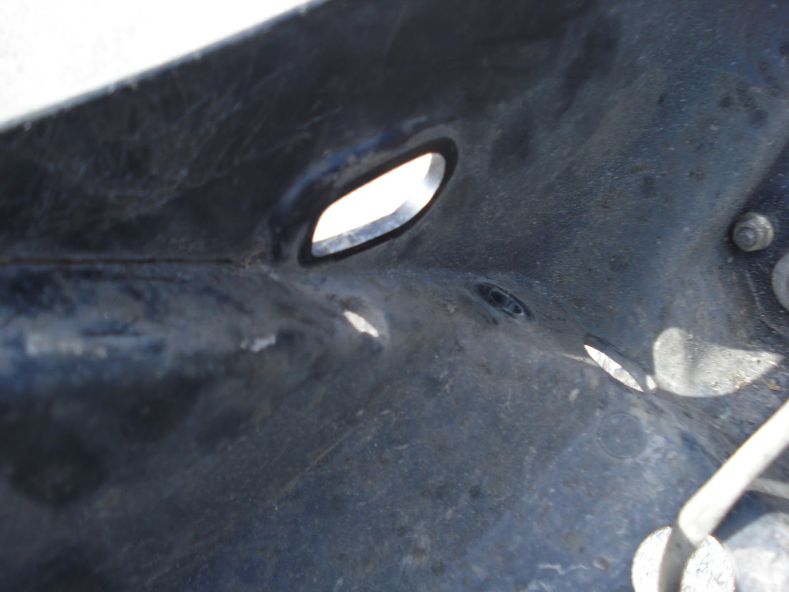
Taking appart the turn signals we found the metal bulb holders were flared into the plastic casing. This would need to be removed so we can move the turn signals elsewhere

unscrewing the brakelight in the back I noticed something pretty suspicious...
The hold on either side of the brake light seem pretty prefect for a bulb holder.


from the other side its pretty obvious that a turn signal could go there. What I think happened is the US required something that forced Kawasaki to make an additional fender and turn signals for their bikes sold in the US but in other markets they had the turn signals already integrated. This makes my job easy because I dont need to make a custom mounting for the turn signals!
taking out the old bulb holder

Fits perfectly!
Securing it in place with a little glue

Redoing and checking the wiring.

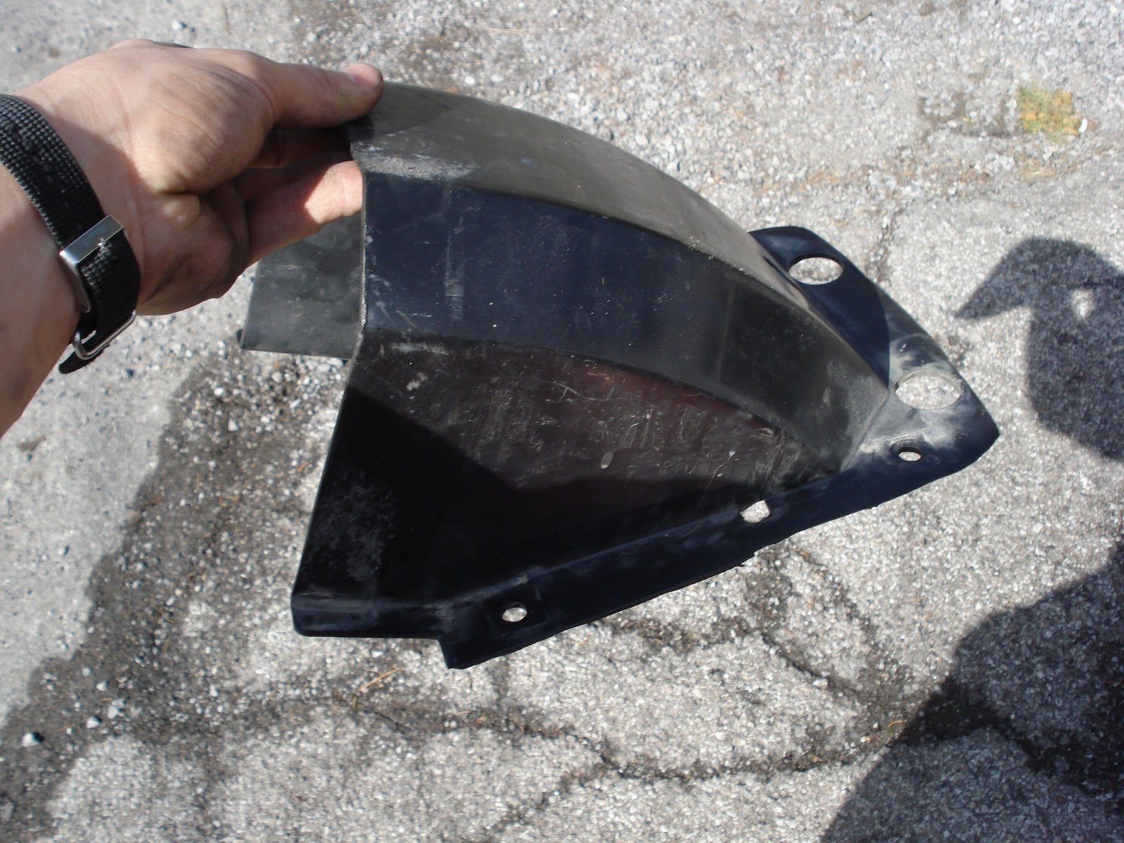
Bingo! We werent quite dont yet however because there needs to be a light to illuminated my license plate at night. I researched online how other people solved this and the most popular and simplest was to mount your plate under the brake light and remove a little pannel on the bottom so the light can shine down.


Super easy. Now all that was left was to trim up the old fender so the underside still protects my bike from rocks and mud and things.
trimming with a utility knife


done! The edges need some cleaning up maybe with a file but Ill do that later
Mike re installing the fender

All cleaned up!

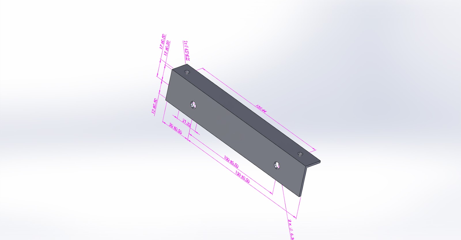
It looks awesome. All thats left is a license plate holder. I have a temporary one on right now but Im going to CAD design a nice one and machine it out  this week.


Simple plate bracket in Solid Works.